
![]()
![]()
|
|
|
|
 | ||||||||||||||||||||
 | ||||||||||||||||
 | ||||||||||||||||
 | ||||||||||||||||
 | ||||||||||||||||
 | ||||||||||||||||
 | ||||||||||||||||
 | ||||||||||||||||
 | ||||||||||||||||
 | ||||||||||||||||||||
 | ||||||||||||||||
 | ||||||||||||||||||||||||||||||||||||||||||||||||||||
 |
 | ||||||||||||||||||||
 | ||||||||||||||||
 |
 | ||||||||||||||||
 | ||||||||||||||||
 | ||||||||||||||||
 | ||||||||||||
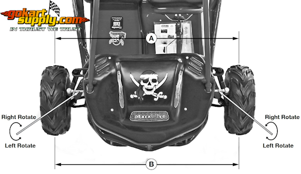
The front wheels should be set with a 'Toe-In' from 1/4 inch to 1/2 inch. At the centerline of the tires, with the wheels pointed straight ahead, measure the Distance A and the Distance B. For proper toe adjustment, Dimension A should be a 1/4 inch to 1/2 inch greater than Dimension B. If dimension A is not 1/8 inch to 1/4 inch greater than dimension B, the front wheels require alignment.
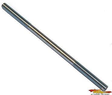
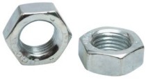
TO MAKE ADJUSTMENTS: Loosen the lock nuts on both sides of Front Tie Rods. Ensure the steering wheel is centered, and adjust Dimension B by equally rotating the tie rods in or out with a wrench.
After adjusting to the desired length, tighten the lock nuts against the Tie Rods.
Recheck the dimensions for proper alignment.
When the steering arm on the steering column is vertical and centered, the front wheels are to be aligned directly forward (not turned). If the wheels are turned when the steering arm is vertical, the steering angle either to the right or left is reduced and the wheels require alignment.
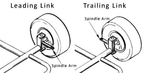
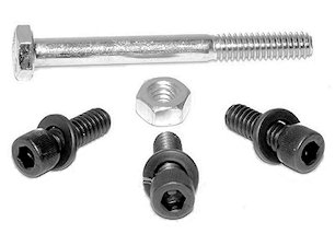
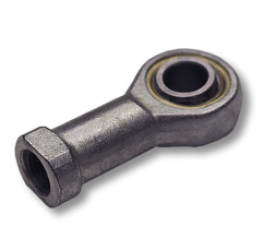
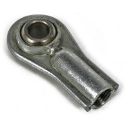
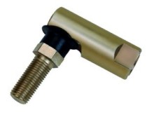
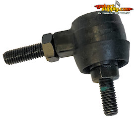
LEADING LINK ALIGNMENT: If the vehicle is equipped with tie rods as shown in Figure 3, adjust as follows: Remove the nuts from both rods at the spindle arm. Loosen and move the jam nut away from both rod ends. To make dimension B smaller, screw both rod ends inward 1 or 2 turns. If B needs to be larger, screw the rod ends outward. Tighten both jam nuts tightly against the rod ends. Replace tie rods in spindle arm and replace nuts. Tighten nuts securely. BOLTS AND NUTS MUST BE IN PLACE AND TIGHT BEFORE CHECKING THE DIMENSIONS. Recheck the distance and repeat the above steps until the dimensions are per instructions above.
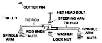
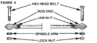
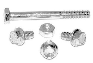
If it's equipped with tie rods as shown above in Figure 4, adjust as follows: Loosen and move the two jam nuts away from the rod ends. To make diminsion B smaller, screw both ends inward on both rods 1 or 2 full turns. If B needs to be larger, screw the rod ends outward. Tighten the jam nuts snugly against the rod ends. Replace the hex head bolts thru the rod ends and spindle arms, and replace the lock nuts. Tighten securely. BOLTS AND NUTS MUST BE IN PLACE AND TIGHT BEFORE CHECKING THE DIMENSIONS. Recheck the distance and repeat the above steps until the dimensions are per paragraph 1 and 2.
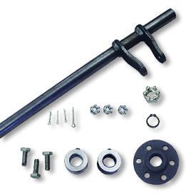
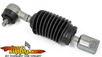
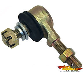
TRAILING LINK ALIGNMENT (as shown in Figure 2): If the vehicle is equipped with tie rods as shown in Figure 2, adjust as follows: Remove the nuts from both rods at the spindle arm. Loosen and move the jam nut away from both of the rod ends. To Make dimension B smaller, screw both rod ends out-ward 1 or 2 full turns. If B needs to be larger, screw the rod ends inward. Tighten securely. BOLTS AND NUTS MUST BE IN PLACE AND TIGHT BEFORE CHECKING THE DIMENSIONS. Recheck the distance and repeat the above steps until the dimensions are per paragraph 1 and 2.
If the vehicle is equipped with tie rods as shown above in Figure 4, adjust as follows: Loosen and move the two jam nuts away from the rod ends. To make diminsion B smaller, screw both ends inward on both rods 1 or 2 full turns. If B needs to be larger, screw the rod ends outward. Tighten the jam nuts snugly against the rod ends. Replace the hex head bolts thru the rod ends and spindle arms, and replace the lock nuts. Tighten securely. BOLTS AND NUTS MUST BE IN PLACE AND TIGHT BEFORE CHECKING THE DIMENSIONS. Recheck the distance and repeat the above steps until the dimensions are per paragraph 1 and 2.
![]()
|
|
Page Last Updated: 05/08/2024
© 1997-2024 Go Kart Supply, Inc